12V – Variable DC Power Supply
In this article, we will discuss about a mini project or DIY (Do It Yourself) project named 12V Variable DC Power Supply for
Electronic hobbyist or beginner in Electronics.

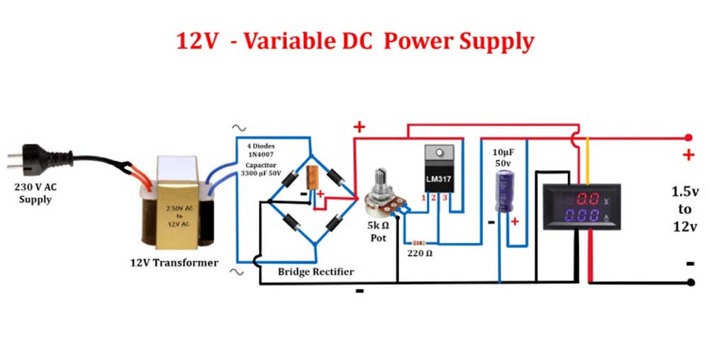
- The circuit showed above, is a very simple but very useful Variable DC Power Supply.
- Using this circuit, we can recharge all rechargeable batteries from 1.2 volt to 12 volt.
- Not only batteries, we can use this power supply as primary voltages to power up or operate the DC equipment and Digital gadgets.
- Will see in detail about how this circuit works.
- This circuit uses a 12V (volt) step down transformer, which will convert 230 volt AC power supply to 12 volt AC power supply.
- Here, in this circuit we used a general purpose transformer or normal transformer.
- The general purpose transformer will have 2 wires in primary section or input section and 2 wires in secondary section or output section.
- Where as the center tapped transformer will have 2 wires in primary section or input section and 3 wires in secondary or output section.
- In multi tapped transformer, the output section will have more than 3 wires.
- For a general purpose transformer, we need to use a bridge rectifier and for center tapped transformer we need to use a full wave rectifier.
- Here we used a bridge rectifier, which uses 4 PN junction diode or silicon rectifier diode with a filter capacitor. This circuit will convert the 12 volt AC to 12 volt DC power supply.
- The diodes we used here is general purpose 1N4007 and a 3300 micro farad 50v capacitor.
- Next, important component we used here is a variable voltage regulator LM317, which is used to vary the output voltages from 1.2 volt to 12 volt.
- This LM317 is capable of handling the current upto 1.5 ampere.
- This LM317 variable voltage regulator is a three terminal component and the three terminals are Variable (1stpin), Vout (2nd pin) and Vin (3rd pin) respectively.
- The DC output from bridge rectifier will be given as input voltage to the third pin of LM317 and the output will taken out from the second pin of LM317 by varying the 5 KΩ(kilo ohm) potentiometer or pot.
- Potentiometer is nothing but a variable resistor where we can vary the resistance value from 0 Ω to its maximum resistance value. In this circuit we can vary from 0 Ω to 5 KΩ (5000Ω)
- With the help of 220 Ω fixed resistor and 5 KΩ variable resistor, the input voltage will be varied from1.2 volt to 12 volt respectively.
- At end of LM317,we will use a capacitor (10 micro farad 50v) for a smoothing operation.
- The fixed resistor and variable resistor don’t have polarity but the capacitor have polarity.
- Also we will connect a digital voltmeter and ammeter for monitoring the voltage and ampere status at end of this circuit.
- For a long run operation, a proper heat sink is recommended to use for LM317 IC in order to avoid over heating issues and it will protect the LM317 IC from damaging.
Also Read: Mobile Chip Level Training in Chennai
Also Read: eMMc Repair Course
Also Read: Laptop Chip-Level Training Course
Also Read: CCTV Training Courses
